https://www.aaastateofplay.com/all-about-ham-radio-for-beginners/
Category Archives: News
Heard on the Grapevine
Brenton VK2MEV has recently been working on a digital signal processing system for ham radio use. The current prototype uses a Raspberry Pi connected to an IC-7200 via the radio’s built in USB interface and to a headset via a USB sound card. Transmission speech processing is performed by the Raspberry Pi and includes adjustable high pass filtering and dynamic range compression. On receive the little Pi is capable of calculating a spectrogram, or waterfall, which is drawn to the Linux framebuffer and displayed on a screen via the HDMI or composite outputs.
Brenton VK2MEV, Josh VK2JOS and Sam VK2AFA are practicing their morse code skills with modern computer and smartphone technology. More details and the results of their progress soon.
The Trans Tasman 160m Contest is held at the end of July. The HRG contest team is evaluating some 1/4 wave vertical antenna options with support by a helium balloon or a kite. The team intends testing both strategies before the contest.
Permitted Equipment For Amateur Use
Ben Hennessy VK5TX
With the recent discussion on the air and the internet about if it is legal to possess equipment that can transmit on frequencies other than the amateur band, the WIA has released the following statement on their website.
http://www.wia.org.au/licenses/licensing/amateurequipment/
Permitted Equipment For Amateur Use
Introduction
This page has been developed for the benefit of members as a result of a number of ACMA compliance activities in recent years, that has left some amateur licensees unsure as to what he or she can possess and operate. The term “operate” for the purposes of the licence conditions means to cause a transmitter to transmit or cease to transmit.
The WIA has argued that these compliance issues are almost in all cases one of behavour (illegal acts) and rather than defining what type of classes of equipment an amateur may possess or operate a more general approach has been agreed.
In Australia, the ACMA has the powers make Standards for radiocommunications equipment (Section 162 of the Radiocommunications Act 1992 (the Act)).
One of the main tenants of the amateur service is technical investigation, experimentation and the like.
In Australia there are no specific standards for equipment manufactured specifically for the world wide amateur market. There are some general technical conditions that apply to every amateur licence. These are contained in the Radiocommunications Licence Conditions (Amateur Licence) Determination No.1 of 1997 (the LCD).
Put simply:
an amateur transmitter, while required to meet certain technical standards, does not have to comply with an Australian Standard, or be “type approved”;
an amateur (other than a Foundation licensee) may build his or her own transmitter;
an amateur (other than a Foundation licensee) may modify a transmitter built for other services to operate on amateur bands;
an amateur must operate any transmitter in accordance with the licence conditions applicable to his or her class of licence;
Therefore, an amateur may possess any piece of equipment manufactured specifically for the global amateur market, provided it is operated in accordance with the type of licence the operators holds, even if the piece of equipment is capable of operating in are certain spectrum segments that are not available in Australia.
Foundation Licence
Essntially, the Foundation Licence is an operator licence that requires a minimum of technicl knowledge that will allow safe operation of a Foundation amateur station.
A radio amateur with a foundation licence can only operate commercially manufactured equipment. And is restricted to defined frquency bands, emission modes and limited to 10 watts transmitter output power. These requirements are contained in Part 6 of the LCD.
Allowed Equipment for Standard and Advanced
The amateur has a licence, the presumption is that the possession is for the purpose of operation, but if the piece of equipment can be operated in accordance with the licence or modified to operate in accordance with the licence, the possession cannot be unlawful, in the absence of other evidence.
An Advance or Standard licensee, may modify a transmitter that is subject to a “Standard” but in doing so the equipment becomes what is known as “Non Standard” and therefore cannot legally be used outside amateur spectrum. Modification means removing or altering components, including the microphone, changing firmware or software features that existed went the device complied with the Standard.
Prohibited Equipment
Should equipment manufactured for the amateur market be modified to operate outside amateur spectrum, it cannot lawfully be operated on the Citzens Bands, or Maritime Bands as equipment used in these Services are required to comply with Australian equipment Standards.
Summary
It is expected that all amateur will act in a responsibe manner (behavour), and comply with there individual licence conditions.
If you have any questions or queries on the use of radio equipment on the amateur bands please send an email the address nationaloffice@wia.org.au setting out your question or concerns.
Page Last Updated: Monday 4 March 2013 at 10:22 hours
What Is A Transverter? Part One
Ben Hennessy VK5TX.
This post will be part of a group explaining the basics about microwave transverters, what they are used for and the details of putting a 23cm transverter system together.
So what is a Transverter and why we use them?
To use frequencies above 1Ghz there is no off the shelf equipment available or the equipment available is expensive so we use a transverter to generate higher frequencies.
Instead of building a 1296Mhz radio from the ground up that will have limited features (one mode, low gain, poor tuning, large size) we can use off the shelf radio packed with features like (all mode, high RX gain, large tuning range and most cases small in size) But these radios normally only transmit up to the high 400Mhz range. We can get around this by using the off the shelf radio as an intermediate frequency to drive a transverter. By using this method one IF radio can be used to drive multiple transverters instead of building a whole radio system for each frequency.
So how does it work?
Before we start talking about how a transverter works we need to take a step backwards and look how a basic 2m 144Mhz SSB radio works.
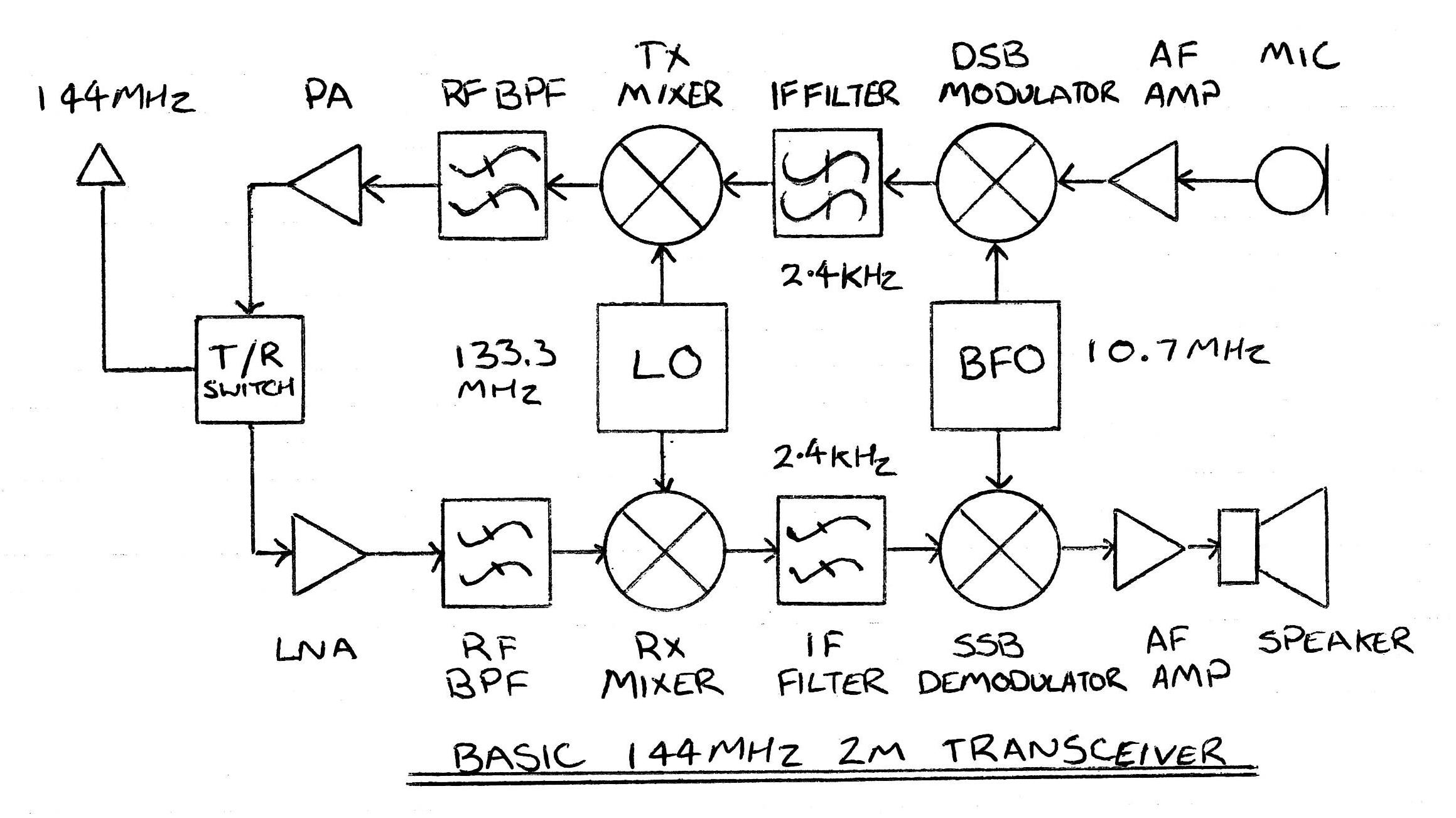
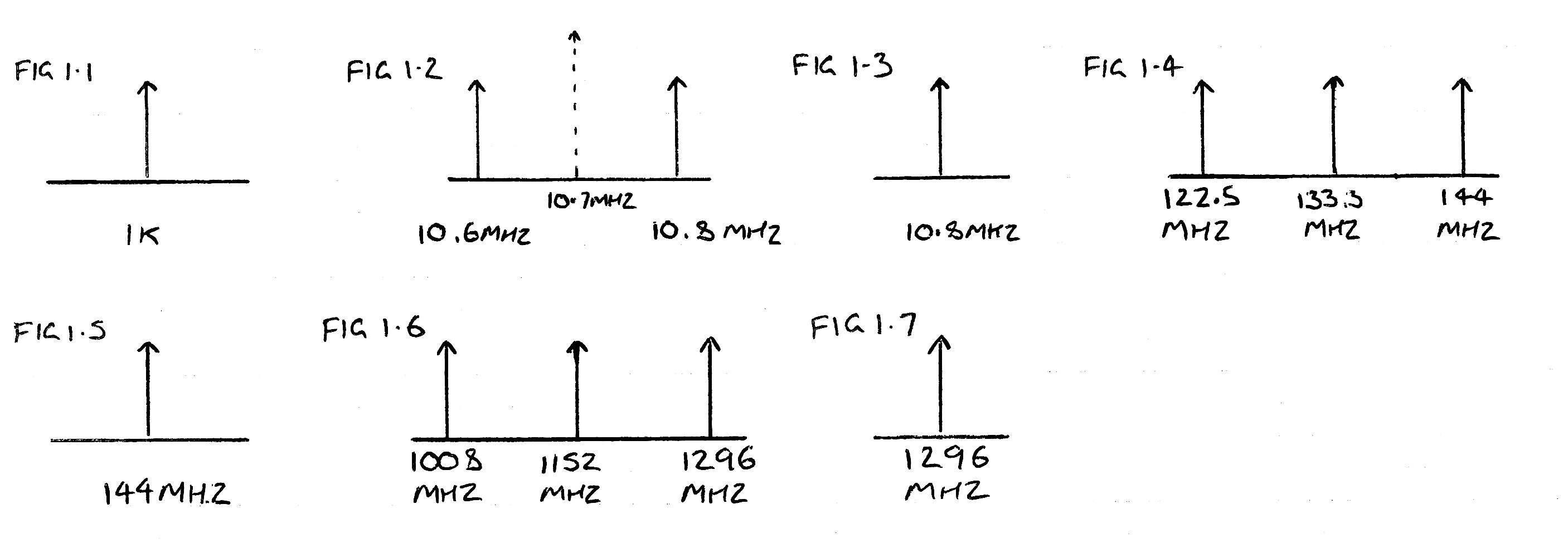
On transmit the sound from the mic (FIG 1.1) is mixed with BFO to produce an Intermediate Frequency (IF typically 455Khz and 10.7Mhz FIG 1.2). The IF is then passed through a filter to convert the DSB into SSB (FIG 1.3). Then the IF signal is then mixed with the local oscillator frequency (FIG 1.4) and passed through a band pass filter to produce the final output frequency (10.7Mhz + 133.3Mhz = 144Mhz FIG 1.5). The signal is amplified and then sent out the antenna port.
On receive the same happens but in reverse. The incoming RF signal is amplified and then mixed with the LO to produce the IF (144Mhz – 133.3Mhz = 10.7Mhz). The IF is passed through a filter and then mixed again with the BFO to produce sound.
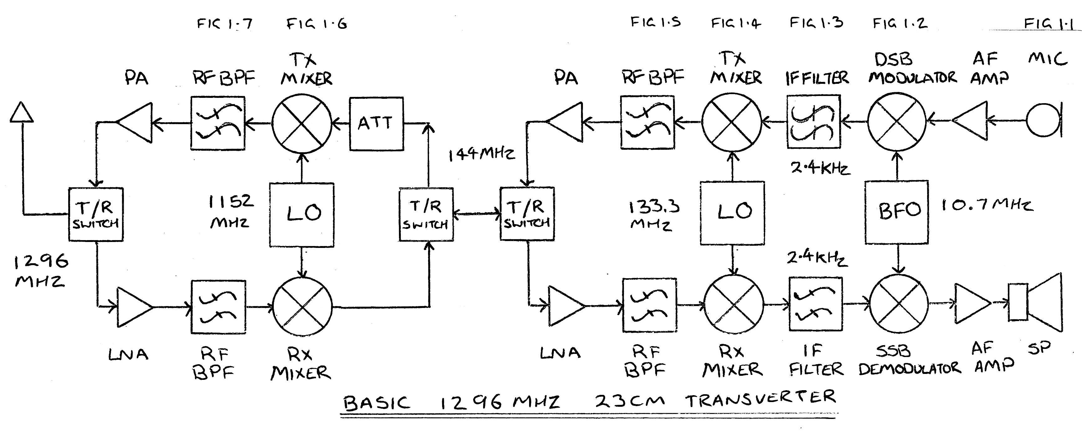
A transverter just an extra stage another with mixer and oscillator. On transmit the output of the 2m radio in is passed through an attenuator to limit the signal low enough to be mixed with the LO of the transverter (144Mhz + 1152Mhz = 1296Mhz FIG 1.6) and passed through a band pass filter to produce the final output frequency (1296Mhz FIG 1.7). The signal is amplified and then sent out the antenna port.
On receive the same happens again. The incoming RF signal is amplified and then mixed with the transverter LO to produce 144Mhz for the radios input.
Transverter building blocks.

A transverter can be broken down into simple building blocks as shown above. More detail of each block is detailed below.
IF Radio
There are some commonly used radios to drive transverters. These radios are small in size, portable and low power. Most users modify their radios to supply a PTT signal over the output RF connection to control the actions of the transverter.
The commonly used radios are:
Yaesu FT-290R
2m all mode.
2.5w high power 0.5w low power.
Battery operated.
Yaesu FT-817
Multi-band all mode.
5w high power 2.5w low power.
Battery operated.
ICOM IC-202
2m SSB/CW.
3.5w.
Battery operated.
Sequencer
The sequencer normally provide two rolls. The first is to turn on parts of the transverter in order with small delay when the radio is TX and then turn them off in the reverse order when RX. This allows relays and amplifiers to power up / down before the signal is applied and stops damage to power amplifiers and LNAs.
For example when the radio is TX the following happens.
Delay 1 is used to switch the RF path from the radio to the TX IF path and disconnect the RX IF path from the radio.
Delay 2 is used to switch off any amplifying stages in the RX path.
Delay 3 is used to switch over the output relay to connect the antenna to the TX path.
Finally Delay 4 is use to turn on the TX power amplifier.
Once the circuit has de-activated the output will turn off in the order they turned on.
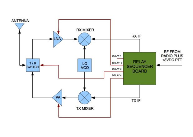
The second function is to attenuate the TX signal low enough not to damage the transverter and separate the TX and RX signals if the transverter has individual RX and TX signal paths.
Trans Tasman 80m Contest 2024
The HRG contest team operated VK2AWX Portable during the Trans Tasman 80m Contest on Saturday July 17 from 6pm to midnight.
Station operators were: Mark VK2IL, Riley VK2KZV, Steve VK2UD, Jamie VK2YCJ and Chris VK2CJB.
On air conditions were excellent with low noise levels and the band was busy with contest traffic.
Final results for VK2AWX Portable were as follows: Contacts made: 222, Points gained: 2024
A special thanks to all members who helped setup and operate the station during the contest and also to those on air stations that made the event enjoyable and a success.
Yes, we came 3rd in the Multi op single transmitter section. CONGRATULATIONS.