Ben Hennessy VK5TX.
This post will be part of a group explaining the basics about microwave transverters, what they are used for and the details of putting a 23cm transverter system together.
So what is a Transverter and why we use them?
To use frequencies above 1Ghz there is no off the shelf equipment available or the equipment available is expensive so we use a transverter to generate higher frequencies.
Instead of building a 1296Mhz radio from the ground up that will have limited features (one mode, low gain, poor tuning, large size) we can use off the shelf radio packed with features like (all mode, high RX gain, large tuning range and most cases small in size) But these radios normally only transmit up to the high 400Mhz range. We can get around this by using the off the shelf radio as an intermediate frequency to drive a transverter. By using this method one IF radio can be used to drive multiple transverters instead of building a whole radio system for each frequency.
So how does it work?
Before we start talking about how a transverter works we need to take a step backwards and look how a basic 2m 144Mhz SSB radio works.
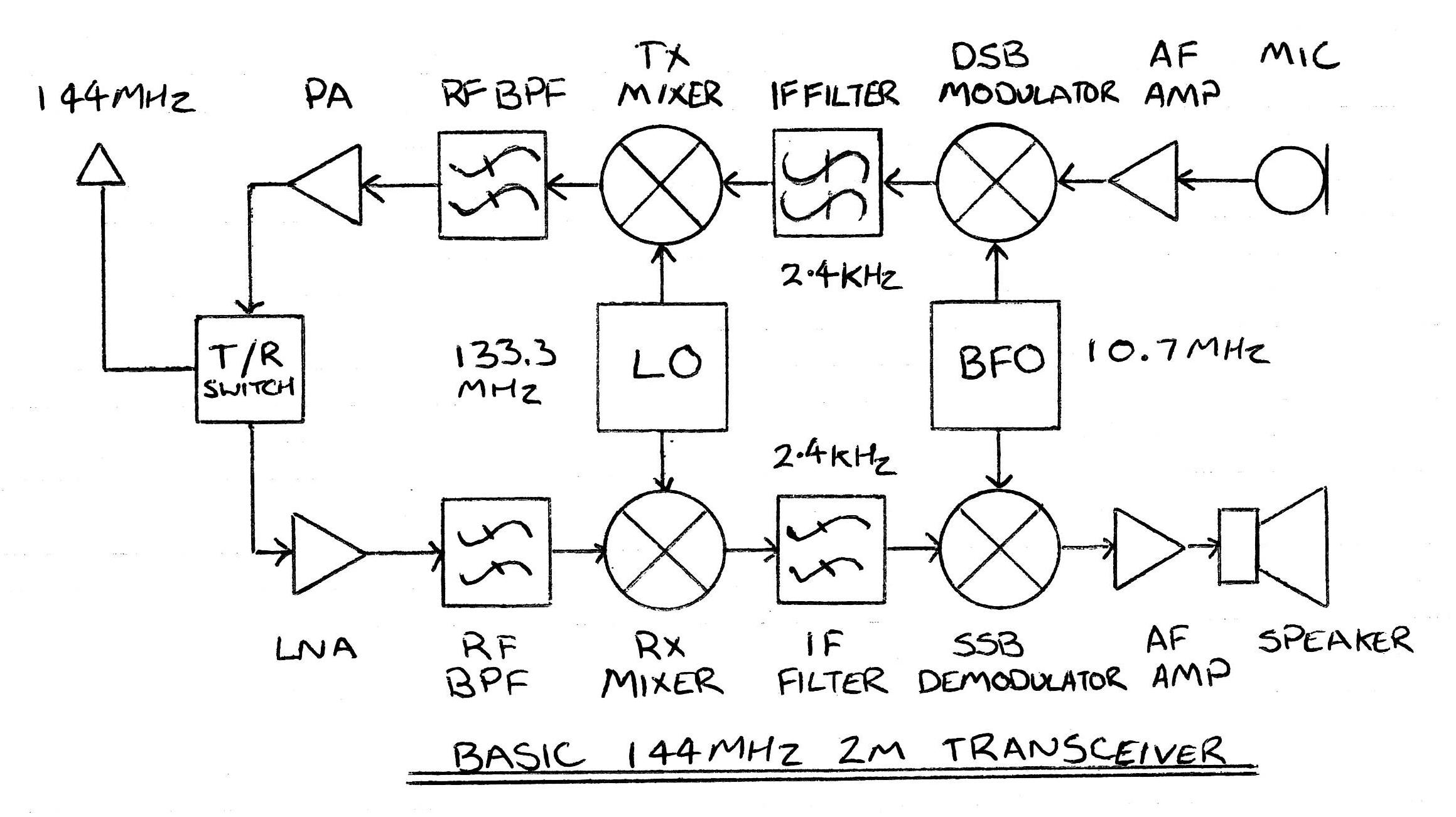
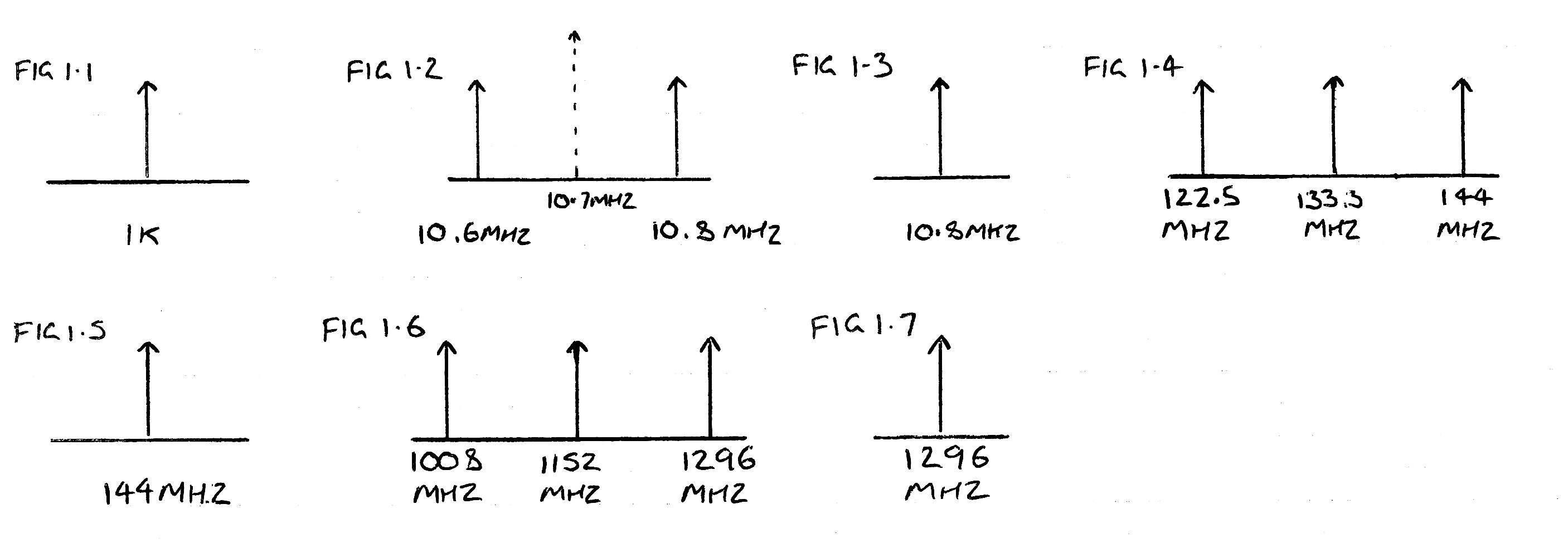
On transmit the sound from the mic (FIG 1.1) is mixed with BFO to produce an Intermediate Frequency (IF typically 455Khz and 10.7Mhz FIG 1.2). The IF is then passed through a filter to convert the DSB into SSB (FIG 1.3). Then the IF signal is then mixed with the local oscillator frequency (FIG 1.4) and passed through a band pass filter to produce the final output frequency (10.7Mhz + 133.3Mhz = 144Mhz FIG 1.5). The signal is amplified and then sent out the antenna port.
On receive the same happens but in reverse. The incoming RF signal is amplified and then mixed with the LO to produce the IF (144Mhz – 133.3Mhz = 10.7Mhz). The IF is passed through a filter and then mixed again with the BFO to produce sound.
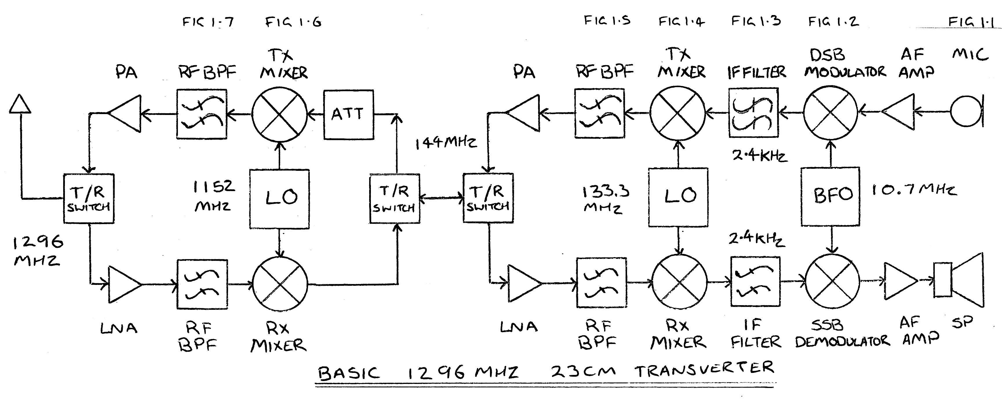
A transverter just an extra stage another with mixer and oscillator. On transmit the output of the 2m radio in is passed through an attenuator to limit the signal low enough to be mixed with the LO of the transverter (144Mhz + 1152Mhz = 1296Mhz FIG 1.6) and passed through a band pass filter to produce the final output frequency (1296Mhz FIG 1.7). The signal is amplified and then sent out the antenna port.
On receive the same happens again. The incoming RF signal is amplified and then mixed with the transverter LO to produce 144Mhz for the radios input.
Transverter building blocks.

A transverter can be broken down into simple building blocks as shown above. More detail of each block is detailed below.
IF Radio
There are some commonly used radios to drive transverters. These radios are small in size, portable and low power. Most users modify their radios to supply a PTT signal over the output RF connection to control the actions of the transverter.
The commonly used radios are:
Yaesu FT-290R
2m all mode.
2.5w high power 0.5w low power.
Battery operated.
Yaesu FT-817
Multi-band all mode.
5w high power 2.5w low power.
Battery operated.
ICOM IC-202
2m SSB/CW.
3.5w.
Battery operated.
Sequencer
The sequencer normally provide two rolls. The first is to turn on parts of the transverter in order with small delay when the radio is TX and then turn them off in the reverse order when RX. This allows relays and amplifiers to power up / down before the signal is applied and stops damage to power amplifiers and LNAs.
For example when the radio is TX the following happens.
Delay 1 is used to switch the RF path from the radio to the TX IF path and disconnect the RX IF path from the radio.
Delay 2 is used to switch off any amplifying stages in the RX path.
Delay 3 is used to switch over the output relay to connect the antenna to the TX path.
Finally Delay 4 is use to turn on the TX power amplifier.
Once the circuit has de-activated the output will turn off in the order they turned on.
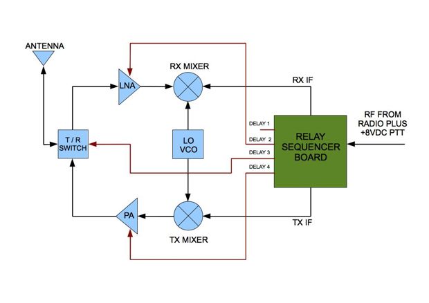
The second function is to attenuate the TX signal low enough not to damage the transverter and separate the TX and RX signals if the transverter has individual RX and TX signal paths.

